What Data Taught Me About Testing Time-Based PLC Logic
What timing exercises taught me about test design, useful failure messages, and building a better way to learn Ladder Logic and Structured Text.
Users and language models kept getting stuck on the same PLC exercises.
Traffic lights, flashers, watchdogs, toggle logic, and debounce: almost every difficult exercise depended on time or remembered state across PLC scans. I expected that logic to be hard. I did not expect the tests and error messages to make it harder.
When I reviewed real user solutions and records of Relay attempts, I found correct programs rejected near timer boundaries. The failure messages often did not explain how to fix the problem. So I rebuilt the tests and error messages for both people and AI.
Humans and AI struggled with many of the same exercises
The pattern became clear when I compared the exercises that took users the most attempts with those that made old Relay retry in my earlier tests. This chart shows the six hardest exercises for users. The bars show the average number of user attempts. Each colored cell shows how many attempts Relay needed in one test run.
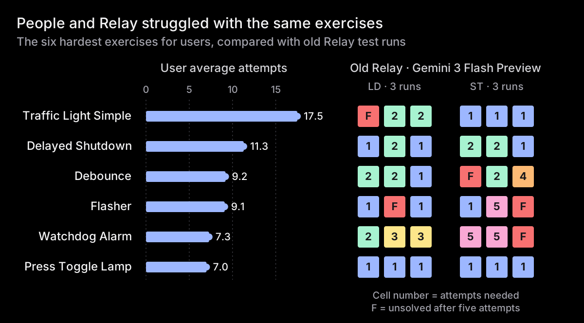
Old Relay used Gemini 3 Flash Preview. F means it still had not passed after five attempts. The user numbers come from real attempts on learn.rungs.dev. The Relay numbers come from controlled tests, so they are not directly comparable. Even so, the same first five exercises were hard for people and Relay. All five depend on time and remembered state across PLC scans.
Press Toggle Lamp is the useful exception. Gemini Flash solved it on the first attempt, but it was the sixth-hardest exercise for users. That does not point to a problem with its tests. The exercise is genuinely difficult because it requires a good understanding of the PLC scan cycle and the order in which instructions run during each scan. For that reason, I moved it down the exercise list.
Timer exercises add another challenge. Timer state, rung order, reset order, and output order can all affect the exact scan when an output changes.
But the records showed something else too: sometimes the student's program was right and the test was wrong.
One common PLC program can be one scan later than another
The Flasher exercise must keep Out_Flash on for one second, then off for one second. I reduced the patterns I found while replaying solutions to three small Ladder Logic programs and ran them against the old and current tests.
The first two diagrams show a 2000ms timer. The incorrect third example deliberately changes its preset to 1900ms. All three start with ACC = 0. To compare the programs, use the old test interval of 100ms between scans. Just before the scan at t=1000ms, Tmr_Cycle.ACC = 900 and Out_Flash = 1.
Timer first, accepted by the old tests:
0
In_Enable
Tmr_Cycle.DN
TON
Timer
Tmr_Cycle
Preset
2000
Accum
0
1
In_Enable
LE
Source A
Tmr_Cycle.ACC
Source B
1000
Out_Flash
At t=1000ms, the timer updates ACC from 900 to 1000. The less-than-or-equal comparison remains true, so Out_Flash stays on.
At t=1100ms, the timer updates ACC to 1100. The output rung reads that new value and turns Out_Flash off. The old tests accepted this program because it matched their expected scan timing. The current tests accept it too.
Same instructions, one scan later, but rejected by the old tests:
0
In_Enable
LE
Source A
Tmr_Cycle.ACC
Source B
1000
Out_Flash
1
In_Enable
Tmr_Cycle.DN
TON
Timer
Tmr_Cycle
Preset
2000
Accum
0
This program uses the same instructions and the same 1000ms and 2000ms values. Only the rung order changes. At t=1000ms, the output rung runs before the timer. It still reads ACC = 900, so Out_Flash stays on. The timer then updates the accumulator to 1000.
At t=1100ms, the output rung reads ACC = 1000. The comparison remains true, so the output stays on for that scan too. It turns off at t=1200ms, after reading the 1100 written during the previous scan. The old test required Out_Flash = 0 from t=1100ms, so it rejected this program.
The current tests accept both programs. With the old test interval, their difference was one 100ms scan. On a PLC, the difference is one execution interval, which depends on how its task is configured.
Why accept the extra scans?
This is a deliberate compromise. With a 100ms scan interval, the second program keeps Out_Flash on for 1200ms instead of 1000ms. Later transitions will fall further behind because resetting and restarting the timer takes additional scans. A continuous task starts its next scan as soon as it finishes the previous one. Its real scan time depends on the controller, program size, other tasks, and communications, but 100ms is deliberately slow for this small example.
The regular Flasher exercise teaches a one-second timer cadence, not precise scan scheduling. Its tests accept this common rung order. A separate hard exercise will teach scan order and long-term drift.
Incorrect, but accepted by the old tests:
0
In_Enable
LE
Source A
Tmr_Cycle.ACC
Source B
900
Out_Flash
1
In_Enable
Tmr_Cycle.DN
TON
Timer
Tmr_Cycle
Preset
1900
Accum
0
This program is not just a different rung order. It changes the full cycle from 2000 to 1900 milliseconds and the ON part from 1000 to 900 milliseconds. Those wrong values compensated for the old test's fixed 100ms scan interval. The program passed every old test even though its timing was wrong. The current tests reject it when Out_Flash turns off at t=940ms.
The problem
The old tests rejected one common rung order, accepted another because it matched the fixed scan interval, and also accepted incorrect timing values. A learning tool should test the behavior it teaches, not code that happens to match one test scan.
The first transition delays described above have nothing to do with DN. The first program turns off at t=1100ms because LE(Tmr_Cycle.ACC, 1000) is still true when ACC = 1000. The second turns off at t=1200ms because its output rung also reads the accumulator from the previous scan.
There is a separate delay at the end of the full 2000ms cycle. Both programs use DN to make the timer rung false. One scan completes the timer, the next scan resets it, and another scan starts timing again. That reset-and-restart sequence moves later cycles another two scans behind.
This version changes both parts: LT removes the inclusive comparison delay, and an explicit reset removes the restart delay when the timer boundary lines up with a scan:
0
In_Enable
TON
Timer
Tmr_Cycle
Preset
2000
Accum
0
1
Tmr_Cycle.DN
Tmr_Cycle
2
In_Enable
LT
Source A
Tmr_Cycle.ACC
Source B
1000
Out_Flash
At t=1000ms, LT(Tmr_Cycle.ACC, 1000) becomes false as soon as the timer writes ACC = 1000, so the first ON phase ends on that scan. At t=2000ms, TON sets DN, RES resets the timer immediately, and the output rung reads ACC = 0. The next ON phase starts during the same scan.
That is better, but it is still not fully drift-resistant. With scans every 30ms, the timer first completes at t=2010ms. Resetting it there discards the extra 10ms, so later boundaries can move farther from the original start time. A truly drift-resistant version keeps one timer running and calculates the current phase from its total elapsed time. I plan to add a separate hard exercise for that distinction.
Tests now declare their scan time
The old test runner used 100ms between every scan, but that value was hidden from the test. A test author could set advance.time to 1s without seeing that the runner would execute ten scans. Students and Relay could read the test but could not see the timing rule behind it.
Test cases can now declare their own scanTime:
- name: catches a fast pulse
  scanTime: 20ms
  steps:
    - in:
        StartButton: 1
      advance:
        time: 200ms
      expect:
        MotorRunning: 1
Here, each scan advances the simulated clock by 20ms. The test still runs immediately; it does not wait for real time. When scanTime is omitted, the default remains 100ms.
Tests near timer boundaries use the finer 20ms pace. This keeps valid scan-order differences small enough to model real execution without allowing large timing errors. A separate Flasher case still runs at 100ms; it rejects solutions that count scans instead of measuring elapsed time.
advance.time must be a multiple of scanTime. advance.scans always means a number of scans, so its elapsed duration changes with the selected pace. The complete syntax is in the scanTime test documentation.
The tests now describe behavior, not one implementation
I rewrote the time-based test cases around three simple rules:
- While a phase is stable, the output must have the required value on every scan.
- When a timer changes state, a short transition period allows valid one-scan differences caused by execution order.
- After that period, the output must hold its new value.
This does not make the exercises easier to pass. Changes caused directly by an input, such as turning off Enable or pressing Stop, must still happen at the required scan. A one-scan error during a stable phase still fails. Timers that finish too early or too late still fail. So do programs with fixed timing values, missing resets, broken restart behavior, or unsafe combinations of outputs.
A failed test now explains what happened
The old runner could report a mismatch like this:
step 4: Out_Seconds — expected 1, got 0It named the output, but did not give enough timing information. A user could not tell whether the output never changed, changed late, or changed and then changed back. A language model received the same incomplete message and often guessed.
The new message is designed to answer those questions directly:
expect failed at step 4 (after scan t=2300ms): Out_Seconds should be 1 at the end of this step; got 0 (inputs: In_Run=1; previous scan at t=2200ms: Out_Seconds=0)A hold checks the value after every scan in a step. The old runner reported only the first bad scan for each output, but the message did not explain what was being checked:
step 3, scan 1/5: Out_Flash — expected 0, got 1The new message says that the output had to remain at that value throughout the step. It also shows the time and previous value:
hold failed at step 3, scan 1/5 (t=1100ms): Out_Flash must remain 0 throughout this step; got 1 (previous scan at t=1000ms: Out_Flash=1)The exact scan shows when the value became wrong. The message includes inputs that were set earlier and are still active. The previous value shows whether the output was already wrong or had just changed. Tests that count scans instead of elapsed time leave milliseconds out because they would not help.
Did it help language models?
I tested old and current Relay on all 60 playable exercises in both Ladder Logic and Structured Text. Each model received the same instructions that Relay used in that version of the product. Its answer was compiled and run against the real exercise tests. It had up to five attempts. No AI judged the answers. A solution passed only when it ran successfully against every test.
Across 360 runs with current Relay—60 exercises, two languages, repeated three times—GPT-5.6 Luna passed 343 on its first attempt and 16 on its second. The final run passed on its third attempt. Nothing required a fourth or fifth attempt, and nothing failed.
The most useful comparison is the Relay users actually had then and now. Old Relay used Gemini 3 Flash Preview. Current Relay uses GPT-5.6 Luna. Each system attempted all 60 exercises three times in Ladder Logic and three times in Structured Text: 360 runs per system.
Looking only at all 60 exercises hides where the improvement happened. The 13 exercises that use timer instructions account for 78 runs with each Relay version: 13 exercises, two languages, repeated three times.
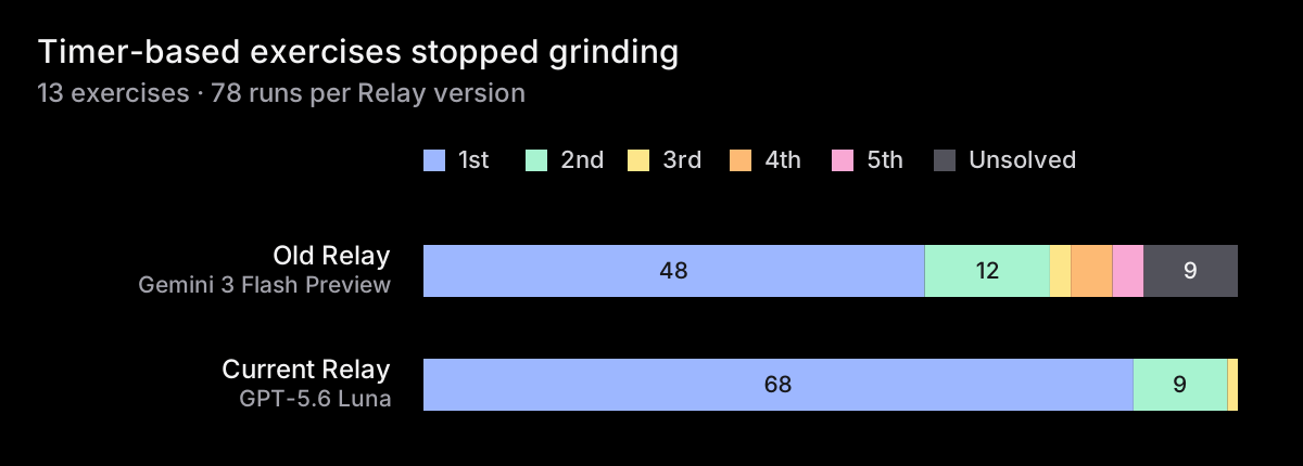
Every current Relay timer-based run passed by its third attempt: 68 of 78 on the first, 9 on the second, and the final one on the third. Old Relay still had nine unsolved runs after five attempts.
The other 47 exercises account for 282 runs per Relay version. They were already much easier for old Relay, and the difference between versions was small.
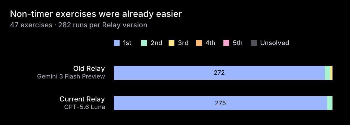
Watchdog Alarm is the clearest example. Old Relay needed 5, 5, F attempts across its three Structured Text runs. Current Relay passed all three ST runs and all three LD runs on the first attempt.
This comparison changes several parts of the product at once. It does not show how much one error message helped by itself. Better first-attempt results mainly show that tests no longer reject valid answers because of exact scan timing. Shorter retry sequences show that when an answer is wrong, the feedback helps with the next attempt.
The remaining failures now point to real programming problems. run-hours, which keeps total run time and carries seconds into minutes, is still hard. In one current Relay run, the model first created a one-second tick that slowly fell behind. The test reported 54 displayed seconds after one simulated minute, and the next attempt fixed the drift. I also ran Gemini 3 Flash Preview on the current stack as a control; when it tried to write to the timer's .ACC value directly, the compiler explained that writing .ACC has no effect and told it to use the timer's reset input. Both models were still solving a hard PLC problem, but each failure gave better direction instead of repeating the same unclear error.
That is the kind of help I want students to get after a failed attempt.
Better feedback for learners
Models were useful because I could run the same exercises many times and see what they did after each failure. The goal, however, was to improve the experience for learners.
A failed exercise should now tell you what was wrong, when it happened, which inputs were active, and whether the output changed since the previous scan. Compiler errors should name the rule and suggest a fix.
If the fix is still unclear, open Relay Chat. Relay sees your code and test results, so you can ask why a rung changed one scan late or what a timer value means.
Try the improved exercises
rungs.dev/learn combines a graphical Ladder editor, a Structured Text editor, realistic scan behavior, exercises that run your code, beginner-friendly compiler messages, automatic tests, and Relay Chat in one browser. It is designed for learning, not as a replacement for PLC engineering software. Every part of it helps you understand why your program behaves the way it does.
If you previously fought the flasher, debounce, watchdog, delayed shutdown, or traffic-light exercises, try them again. The timers are still real. The grading is now fairer, and the feedback is much more useful.